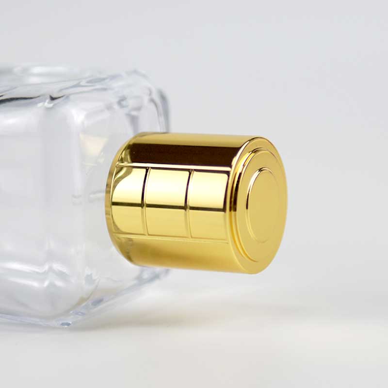
When fitting a removable zinc alloy perfume cap to a bottle, where should the caliper jaws go? First, install the spray pump and collar on the bottle as they will be used. Then identify the surfaces that the cap insert will contact. For a zinc alloy cap, check three interfaces separately: bottle neck to pump, bottle-top assembly to insert, and insert to metal shell.
First, locate the contact between the bottle top and insert
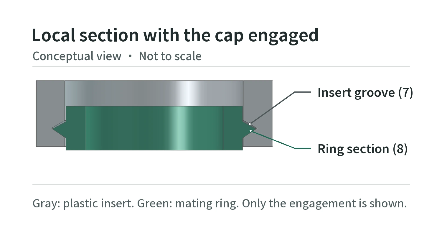
In the illustrated design, the spray pump is secured to the bottle neck, and a mating ring surrounds the pump’s fixed mounting section. When the cap is fitted, groove 7 inside the insert engages lower section 8 of the mating ring. The outer shell fits over the insert. The local section view reveals the contact between the groove and ring. Both the insert and outer shell are open at both ends in this example, which illustrates the groove engagement.
If a bottle drawing specifies FEA 15, first check the glass neck finish and pump mounting method against the relevant drawing. Then locate the surfaces that the cap actually contacts after assembly. Checking the nominal neck specification is only part of the task. You also need to confirm how the selected pump, collar, and cap fit together. If the cap grips a cylindrical surface, mark the measurement points on the section it actually grips.
Measure the bottle top, insert, and metal shell separately
Start with the section where the bottle top contacts the insert. Install the pump and collar in their normal operating positions. If the mating area has a measurable cylindrical section, place the outside jaws at the same height. Bring them gently against opposite sides along a line through the axis, and record the outside diameter at that section. If the profile is not round, measure between the two points specified on the drawing and record their orientation. Use the same reference surface specified on the drawing, such as a defined locating plane on the bottle shoulder. Record the height of the mating area above it. Where the collar has a slope or step, mark the measurement points on the actual contact surface. Moving slightly onto an adjacent slope gives a reading for a different section.
Record the assembly state as well. The mating ring in this example has a gap that closes as the insert snaps into place. Label an outside-diameter reading taken with the cap removed as “pump installed, cap removed.” Check the profile with the cap engaged separately in the fully assembled state.
Measure the inside of the insert. If the mating surface is an accessible cylindrical section, gently touch both walls with the inside jaws at the same cross-section. For an internal groove like the one illustrated, use the end face specified on the drawing as the reference. Mark which side of the groove you are measuring to. If standard jaws only reach the entrance, the reading is the entrance dimension. For a narrow groove, use specialized jaws that can reach the measurement surface, or verify it through section or profile measurement. Take the reading as soon as the jaws make contact, without spreading the insert.
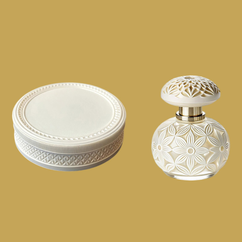
The measurement points differ for an insert that grips the collar with shallow ribs. The example below uses Wbmetal’s demonstration model of an insert with a round opening and three ribs. First, mark the depth from the opening’s end face to the contact section on the component drawing. Then locate the three rib crests that rise toward the center at that section. If the caliper jaws touch the bore walls between the ribs, the reading is the distance between those walls. To check whether the collar will fit, compare its outside profile with the positions of all three rib crests. Then trial-fit the actual collar.

Next, measure the outside of the insert. Check the locating section that enters the shell, the actual stop surface, and the corresponding profile. Where there are ribs or bosses, mark the two points to measure across on the drawing. If the insert is already secured and removal would damage it, refer to the component drawing or a separate sample.
Inside the metal shell, measure the space that receives the insert. Match the insert’s outer locating section to the corresponding section inside the shell. Then measure the inside diameter or width there. For depth measurements, seat the depth gauge base firmly on the end face specified on the drawing. Measure to the step or locating surface against which the insert actually rests. If the insert stops at a step, the total depth to the inside top of the shell does not establish where it seats. State on the drawing and measurement record whether the part is unfinished or has its final surface finish. Use caps in the same condition for trial fitting.
With the cap fitted, measure actuator clearance and the gap below the rim
For a metal cap with a closed top, check the clearance above the actuator once the cap is fully seated. Use an assembly section that includes the actual actuator. Measure from its highest point to the cap’s inner top surface directly above it, parallel to the bottle axis, with the actuator unpressed. If there is a local projection inside the cap, also check where it comes closest to the actuator. During trial assembly, watch for contact with the actuator as the cap moves into place.
Next, check the gap below the cap rim. If the drawing uses the bottle shoulder or collar end face as the visual reference, measure at the specified orientation. Take the distance from the cap rim to that reference surface along the bottle axis. A feeler gauge can provide an initial check of the axial gap if the two surfaces are approximately parallel and approximately perpendicular to the bottle axis. It must slide in gently without lifting the cap. A local gap measured with a feeler gauge at a sloped surface cannot be recorded directly as an axial distance. For sloped surfaces or areas the tool cannot reach, use the assembly drawing or profile measurement. For an irregularly shaped cap, record readings at the orientations specified on the drawing. If the cap tilts or does not seat fully, note which side is raised and where the cap stops. Then recheck the mating areas, actuator, and cap rim.
Record measurement locations together with the assembly state
Start the record with the drawing number and revision used, for example, “Fit inspection drawing FIT-01, Rev. A” (an example identifier). Record readings in mm, and update the corresponding drawing reference when the pump or insert changes. The reading column below is left for measurements from actual samples.
| Measurement | Location or reference | Assembly state | Tool or method | Reading (mm) |
|---|---|---|---|---|
| Outside diameter of the bottle-top mating section | Opposite outer surfaces at the mating cross-section marked on the drawing | Pump and mating ring installed; cap removed | Outside caliper jaws | To be recorded |
| Insert groove position | From the end face specified on the insert drawing to the specified side of the groove | Insert on its own | A depth-measuring tool that can reach the surface, or profile measurement | To be recorded |
| Insert seating depth inside the shell | From the specified end face at the shell opening to the insert stop surface | Final surface finish applied; insert not installed | Depth gauge | To be recorded |
| Clearance above the actuator | From the actuator’s highest point to the cap’s inner top surface directly above it, along the bottle axis | Closed-top cap fully seated; actuator unpressed | Check the assembly section | To be recorded |
| Gap between the cap rim and bottle shoulder | Axial distance between the two surfaces at the orientation specified on the drawing | Cap fully seated | Use a feeler gauge if the surfaces are approximately parallel and perpendicular to the bottle axis, and it slides in gently without lifting the cap. Otherwise, use the assembly drawing or profile measurement. | To be recorded |
If a measurement falls on a groove edge, curved surface, or local rib, mark the point on a section view or photograph. When the pump or insert revision changes, return to the same measurement point to identify which component and section have changed.